SHIP DETAILED DESIGN
Improving work efficiency in the factory, Maximizing Material utilization, Minimize material wastage.
Detailed design provides a comprehensive reference for factory workers. It is an integration of all technical information needed for the fabrication of a certain structure including outfitting. It includes production design and strategy which will make the job in the factory fast, easy and efficient. Material estimation is realistic, thus, optimizing the cost and reduce material wastage.
Hull Design
TECHNICAL CAPABILITY SUPPLEMENTED WITH 3D TECHNOLOGY
TTSP's structural detailed drawings are prepared using data from upstream design, supplemented by international rules and standards for shipbuilding. The drawings include technical information like scantlings, dimensions, material type/grade, welding size/type, sections, and details. Their main purpose is to ensure the integrity of the ship's structure and provide a reference for Hull Production designers that's easy to comprehend. Production drawings and data are produced using structural detailed drawings to facilitate effective material ordering, NC data for efficient steel material utilization, and a comprehensive reference for factory workers during installation. Our use of 3D technology makes detailed design easy and comprehensible, allowing us to determine information like hull weight, center of gravity, and welding length with ease.
- Structural Detailing (Yard Plan) – Integration of all technical inputs into a set of detailed drawings ensuring the integrity of hull structure of the ship and other floating structures.
- Working Plan – Design of assembly strategy per block according to the factory standard and capacity of lifting equipment. It includes the piece naming, welding type and 3D simulation of installation process for easy reference for factory workers.
- Mould Lofting – Creation of the actual profile of each hull piece including the necessary markings and attributes. Bending information, end shape of section-steel, bending patterns for steel plates, jig plan and draft marks are also products of mould lofting.
- Nesting – Preparation of Numerical Control (NC) data using the product of mould lofting to ensure efficiency of material utilization.
- Cutting Plan – Preparation of material estimates for material order. Its aim is to maximize the steel material yield ratio and minimize the material scrap and waste.
Outfitting Design
TECHNICAL CAPABILITY SUPPLEMENTED WITH 3D TECHNOLOGY
At TTSP, our Machinery, Outfitting, and Electrical Design departments work together to ensure that every ship we design is equipped with the necessary equipment to fulfill its purpose. Our Machinery department is responsible for selecting the right machinery and equipment for the ship. Meanwhile, our Outfitting department designs the outfitting of the ship to ensure safety, workability, and compliance with international standards. The Electrical department takes care of the ship's power requirements and designs the necessary electrical equipment and apparatus, including navigational apparatus. By working together, our departments ensure that every ship we design meets our clients' needs while also adhering to the highest safety and quality standards.
- Hull & Accommodation Outfitting – Design of mooring equipment, cargo gears, steering gear, ventilation system in cargo hold, passage, working stages, handrails on weather deck; accommodation and pilot ladders, radar mast and fore mast, steering mechanisms, arrangement of safety equipment, rescue and lifeboat.
- Hull Piping – Diagram and piping arrangement of ballast pipes and other piping systems outside accommodation and engine room area.
- Accommodation Piping – Piping diagram and arrangement of all piping systems in accommodation area including HVAC.
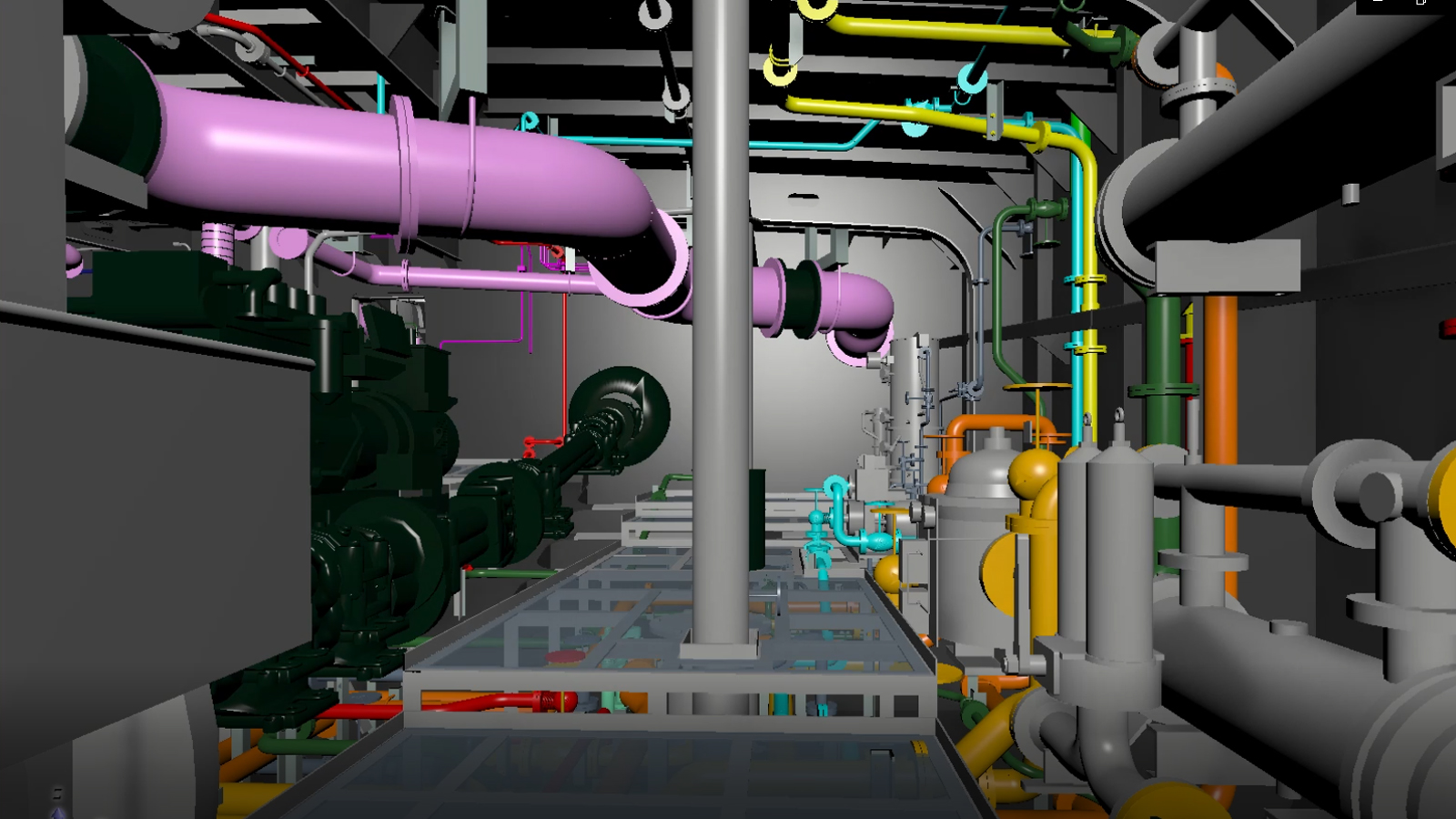
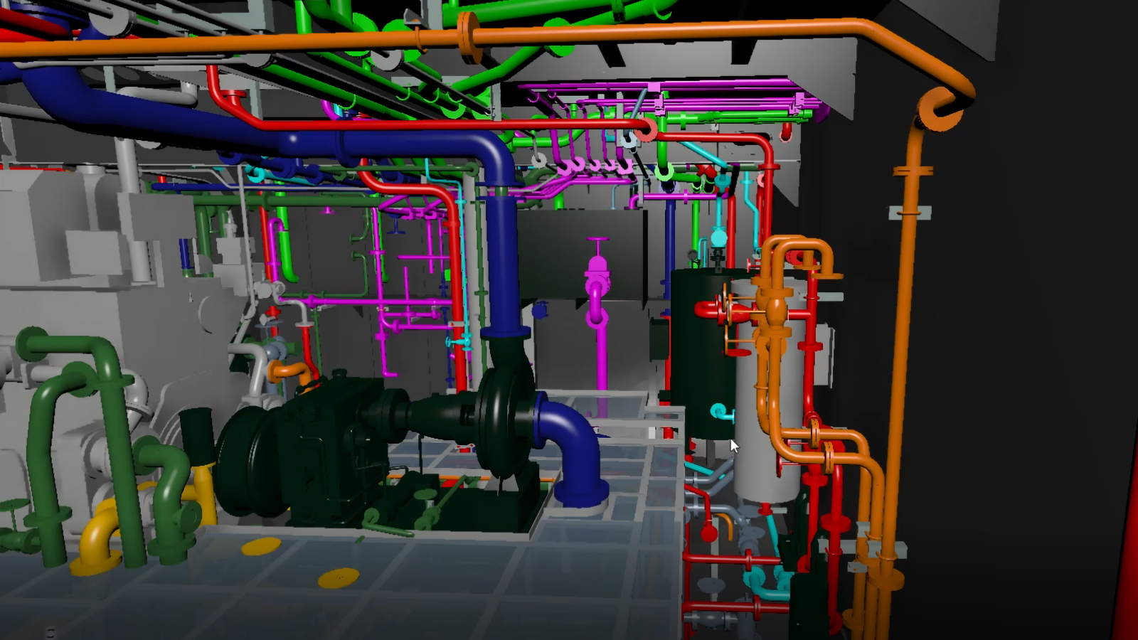
- Machinery Piping – Arrangement of machinery equipment, piping diagram and arrangement inside the Engine Room.
- Machinery Outfitting – Arrangement of outfitting and ventilation inside engine room and funnel
- Electrical –Wiring diagram for lighting, power, automation, navigation and communication system. Arrangement of electrical equipment, design of cableways and electric seat.
RETROFITTING
& REVERSE ENGINEERING
For Ships and Other Structures
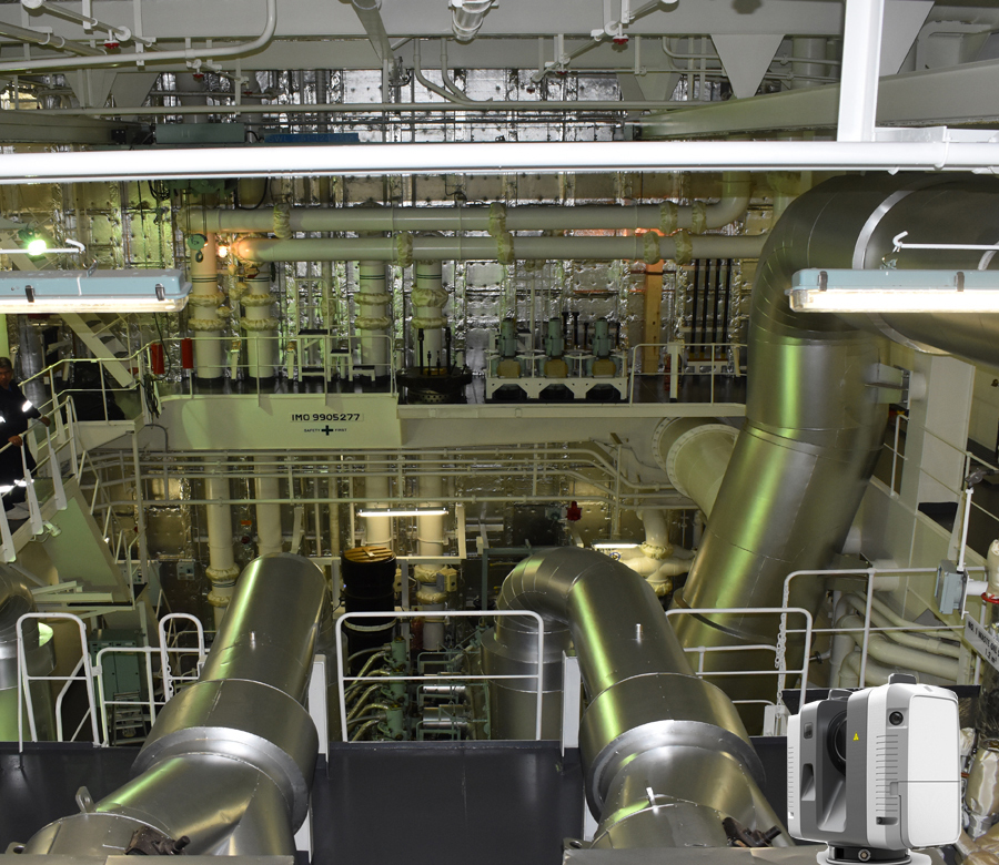
Due to environmental requirement, old vessels need to adopt Ballast Water Management System (BWMS) and SOX Scrubber in order to continue to operate. Installation of these additional equipment and related rectifications onboard is done by retrofitting. Retrofitting requires high technical skills and special tools such as 3D Laser Scanner and 3D software. Due to time constraints during rectifications and installation of new equipment, piping and outfitting, proper planning and precession is a must.
TTSP have done more than 50 projects for BWMS and SOX Scrubber retrofitting. Retrofitting can also be done to structures other than ships like plants and factories. In most cases, old structures have no more available as-built plans. There are also instances where there are rectifications onsite which are not reflected to the as-built plans, thus, reliability and accuracy are of great concerns – Reversed engineering, with the use of 3D Laser Scanner, is the solution to generate the needed set of plans as per actual scenario of the structure.
Initial Analysis
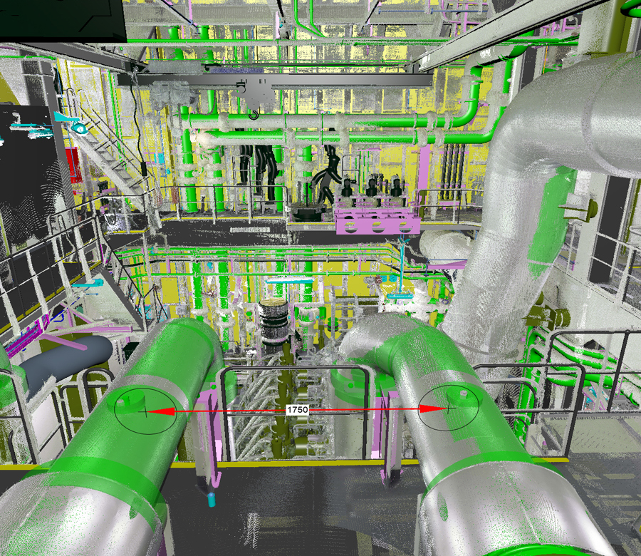
Every project in reverse engineering starts from conducting initial analysis of the current condition of the existing structure. Existing 2D drawings might be insufficient to verify the reliability of the actual structure, the use of 3D Laser Scanning is the best solution to create a digital replica to determine the following:
- appropriate location of additional equipment
- necessary rectifications of the existing structures
- tapping points of new piping necessary for the equipment to run
- existing pipe material
3D Model (Full Set)
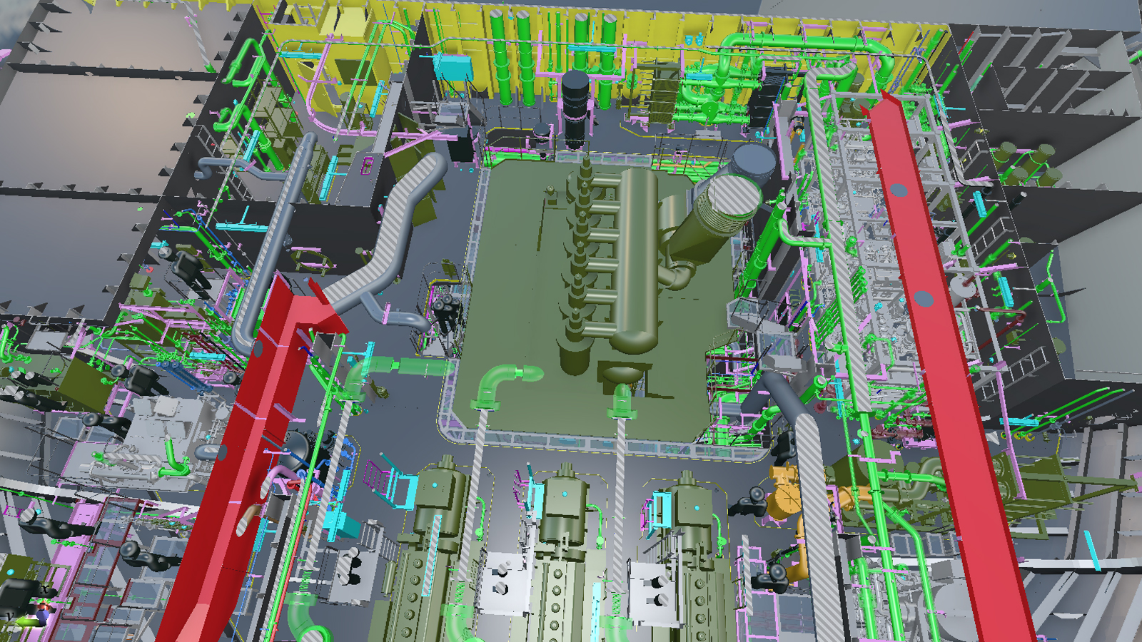
With the use of CADMATIC – Outfitting, a multi-3D tool, well-experienced engineers will start with the implementation of the analysis and creation of 3D model. Everything is thoroughly done using the cadmatic software, equipment modeling, pipe & pipe support modeling, gratings and seat modeling, and all. 3D model is provided to the customer to have a conceptual image of the design, for wider visualization and for advance checking and confirmation. Thus, it eases in improving the quality of the design at the early stage of the project.
Detailed & Production Drawings
After finalization of the 3D model, it will now proceed to the output of detailed and production drawings. Detailed and production drawings will provide inputs to the customer for material ordering and guide the factory workers to properly interpret installation details and at the same time provide data for factory production. Thus, it makes the factory works easier and faster. With the use of 3D model, it surely increases the quality of their work.
3D LASER SCANNING
Capturing Reality Images for Engineering Applications
One of the sophisticated technology, 3D Laser Scanning captures the actual picture of structures using fast and accurate laser measurements, creating a virtual world of an existing environment. It produces millions of point cloud data which can be processed then converted into vector data and 3D model using 3D software. The 3D model output will be used as input for an accurate engineering designs and decisions. 3D Laser Scanning is also applicable to preserve heritage sites, museums, etc.
TTSP can deliver to output the following:
2D AS-BUILT DRAWINGS
Detailed elevation, section & plan drawings can be produced to conventional drawing standards.
3D POINTCLOUD DATA
The millions of 3D points captured are often unified and delivered directly to the client.
3D MODELS
Parametric 3D models can be created to allow clients the benefit of 3D capability.
360° IMAGERY
360-degree images are captured at each scan station allowing data examination in virtual environment.
REVERSE ENGINEERING
3D Laser Scanning updates plans for better designs and rule conformity in renovations.
Furthermore, 3D Laser Scanning service guarantees the following :
- Cost-efficient, quick, and accurate 3D capture of as-build geometry of large structures and spaces
- 3D documentation of complex installations of ships and other structures
- Quick processing of data ready to use and compatible in all commonly used CAD software
- Precise creation of 3D models and reliability of data
- Avoid re-work due to comprehensive and accurate 3D model
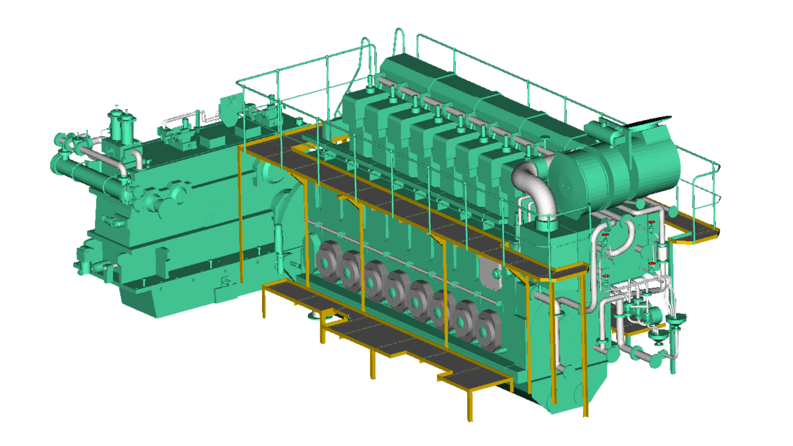
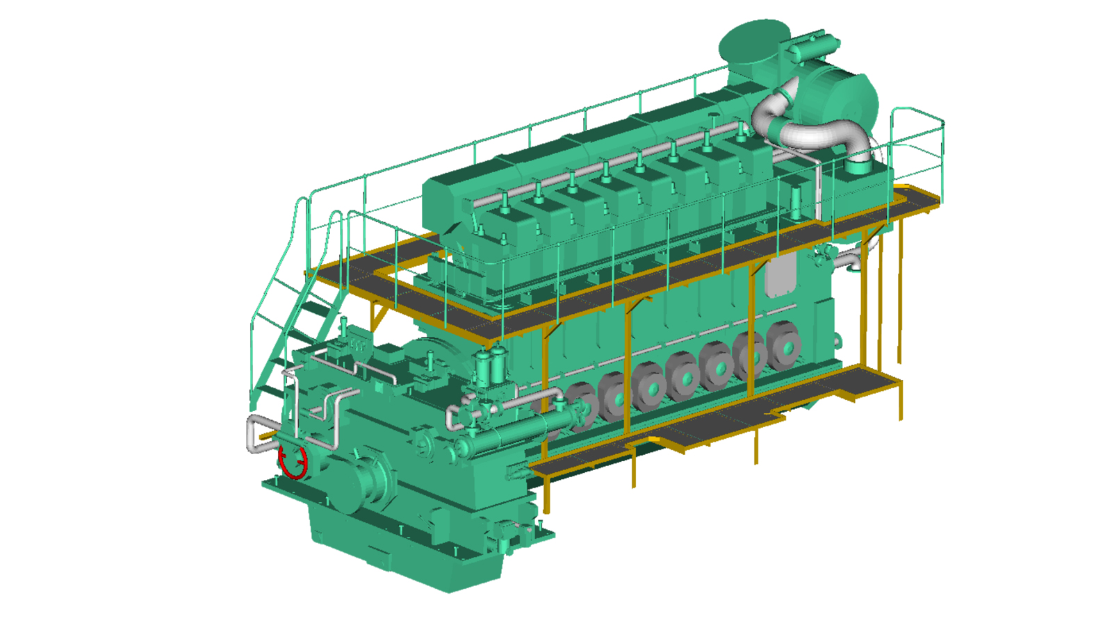
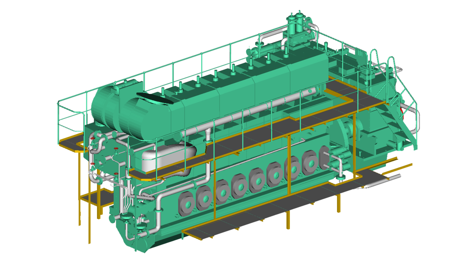
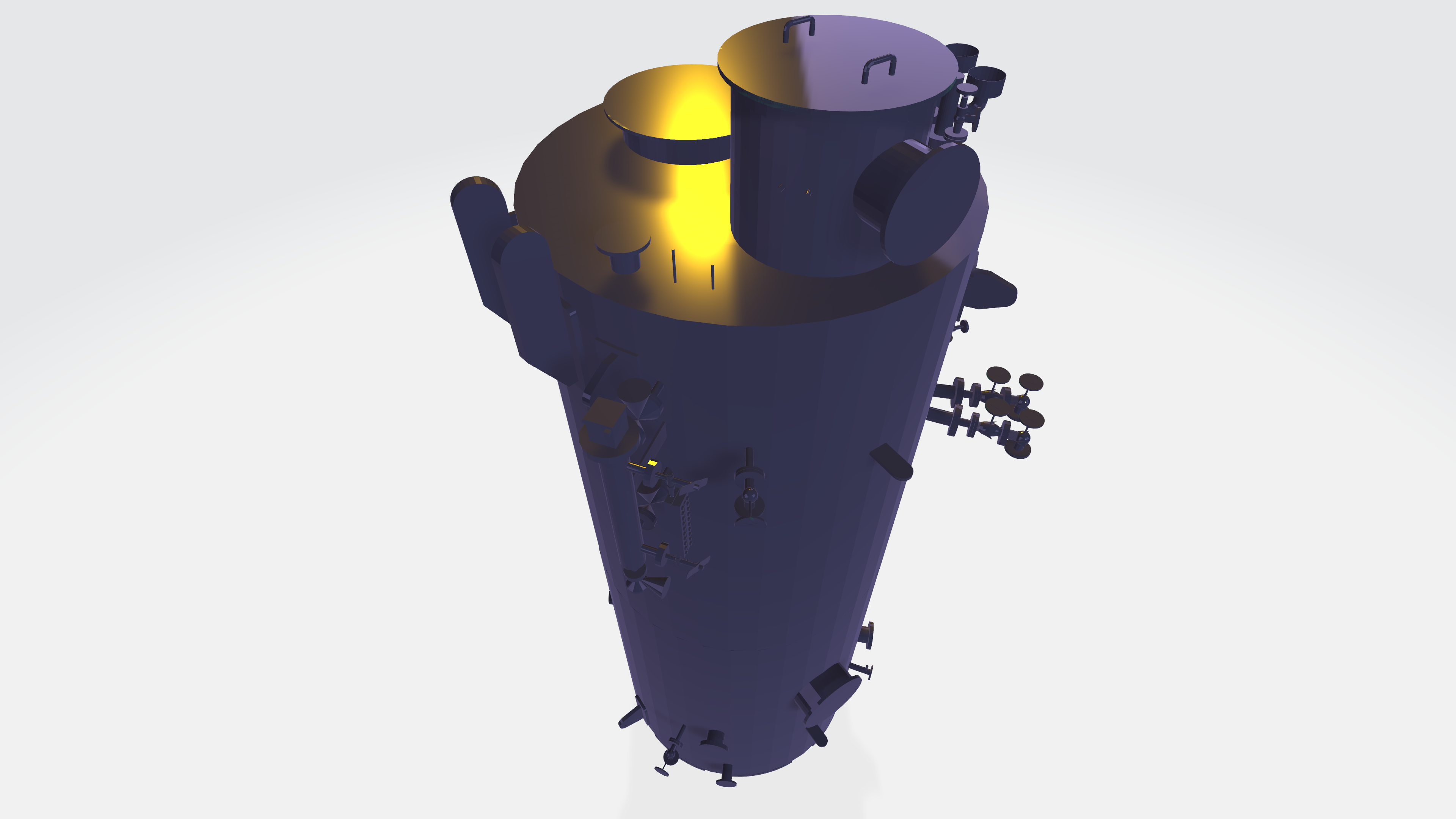
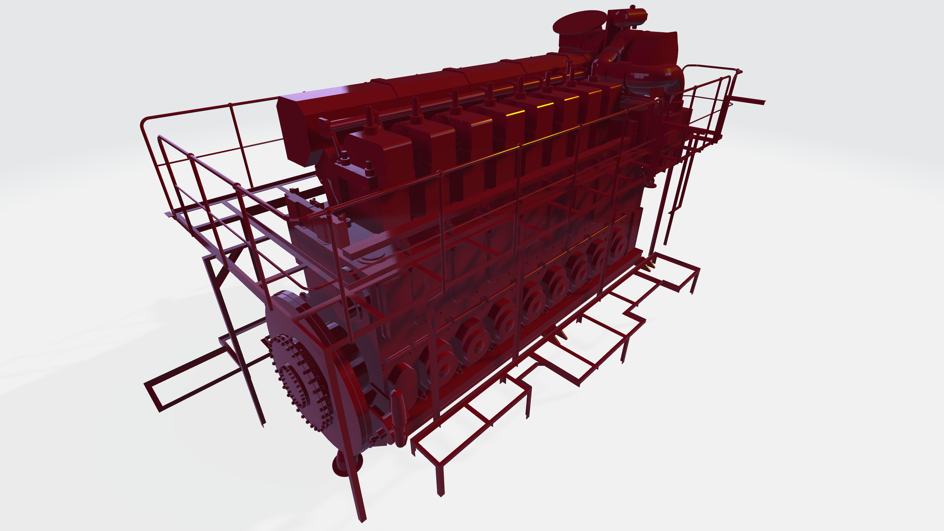
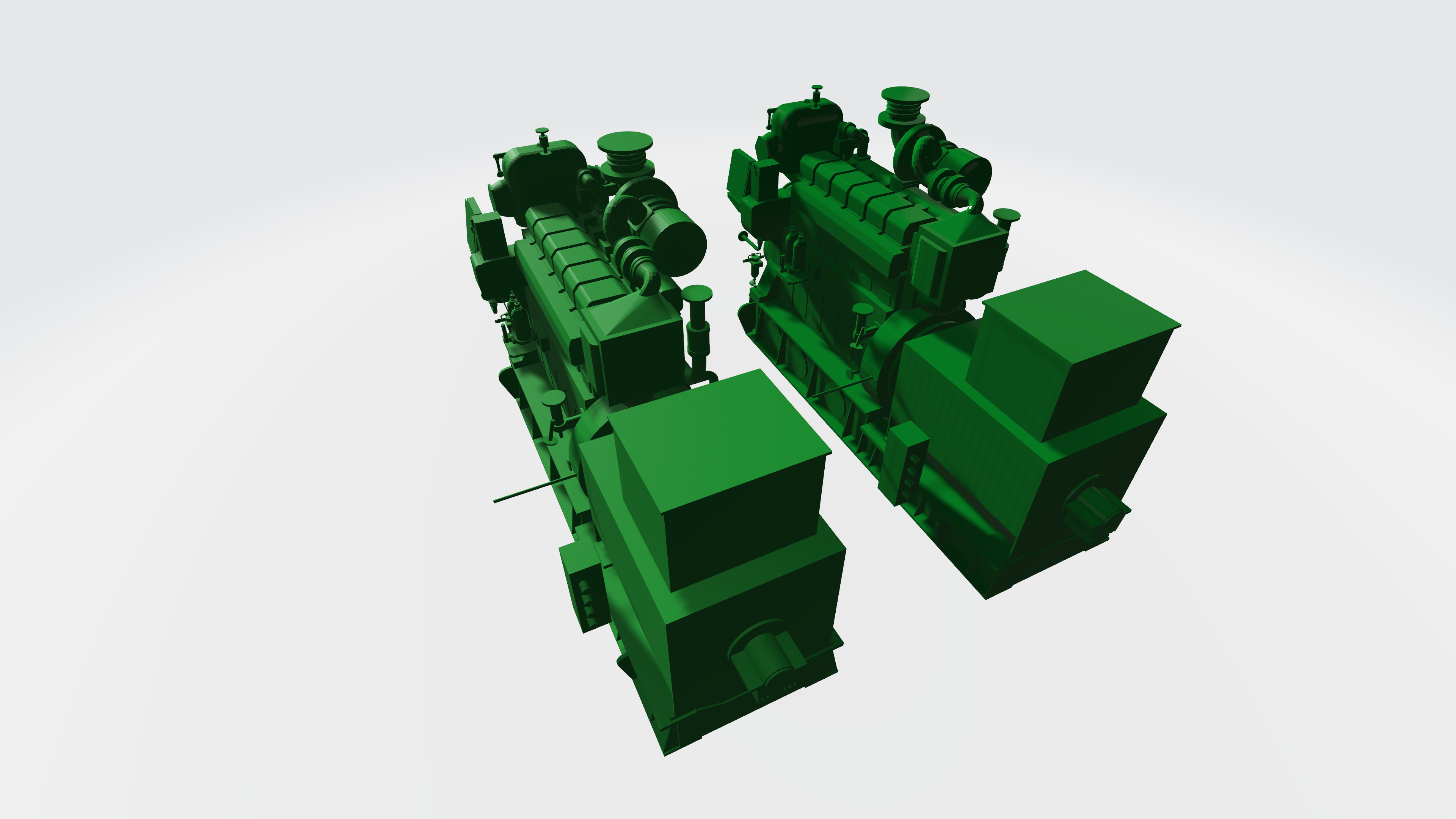
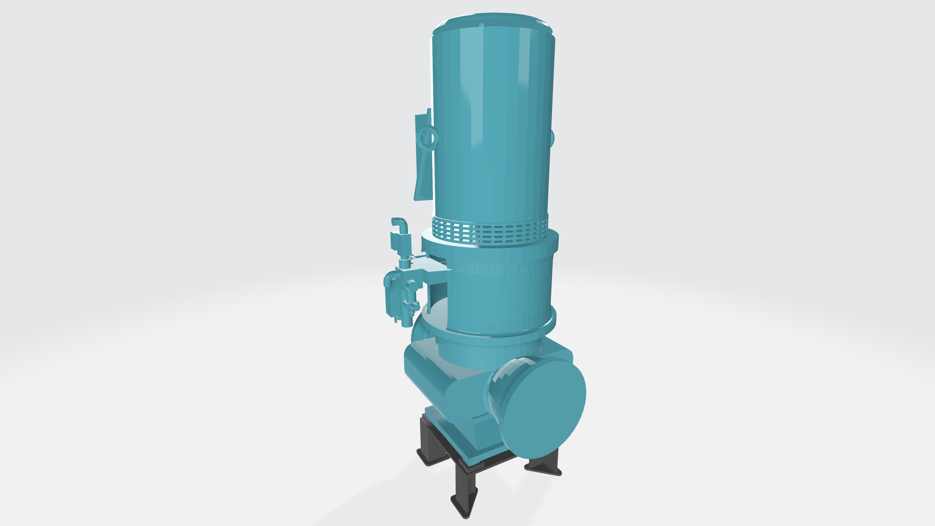
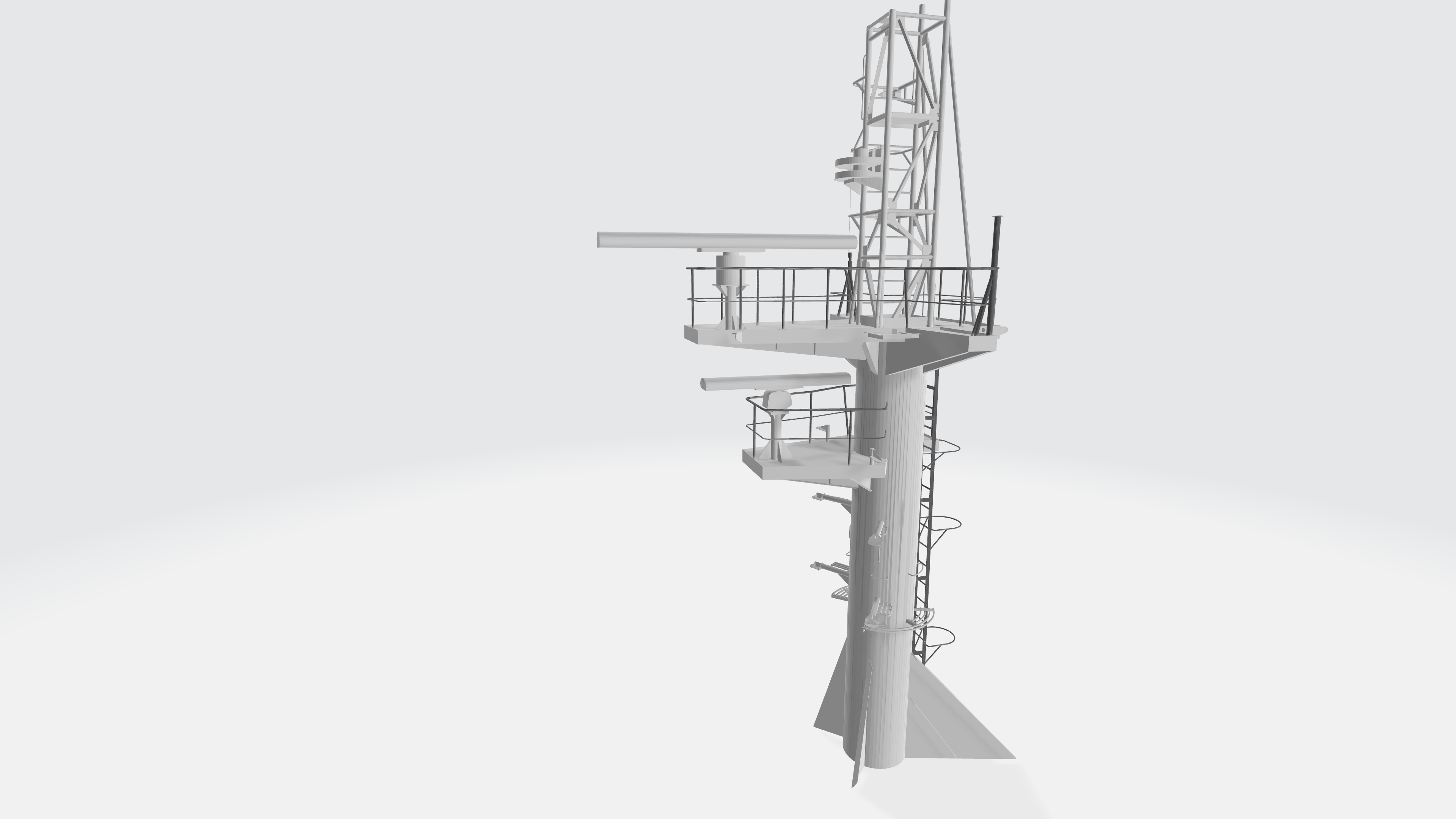
EQUIPMENT 3D MODELING
& LIBRARY CATALOGUE MAKING
Advancing towards Digital Innovation
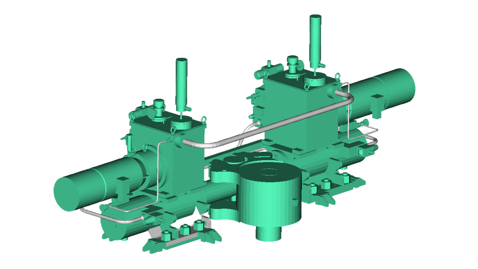
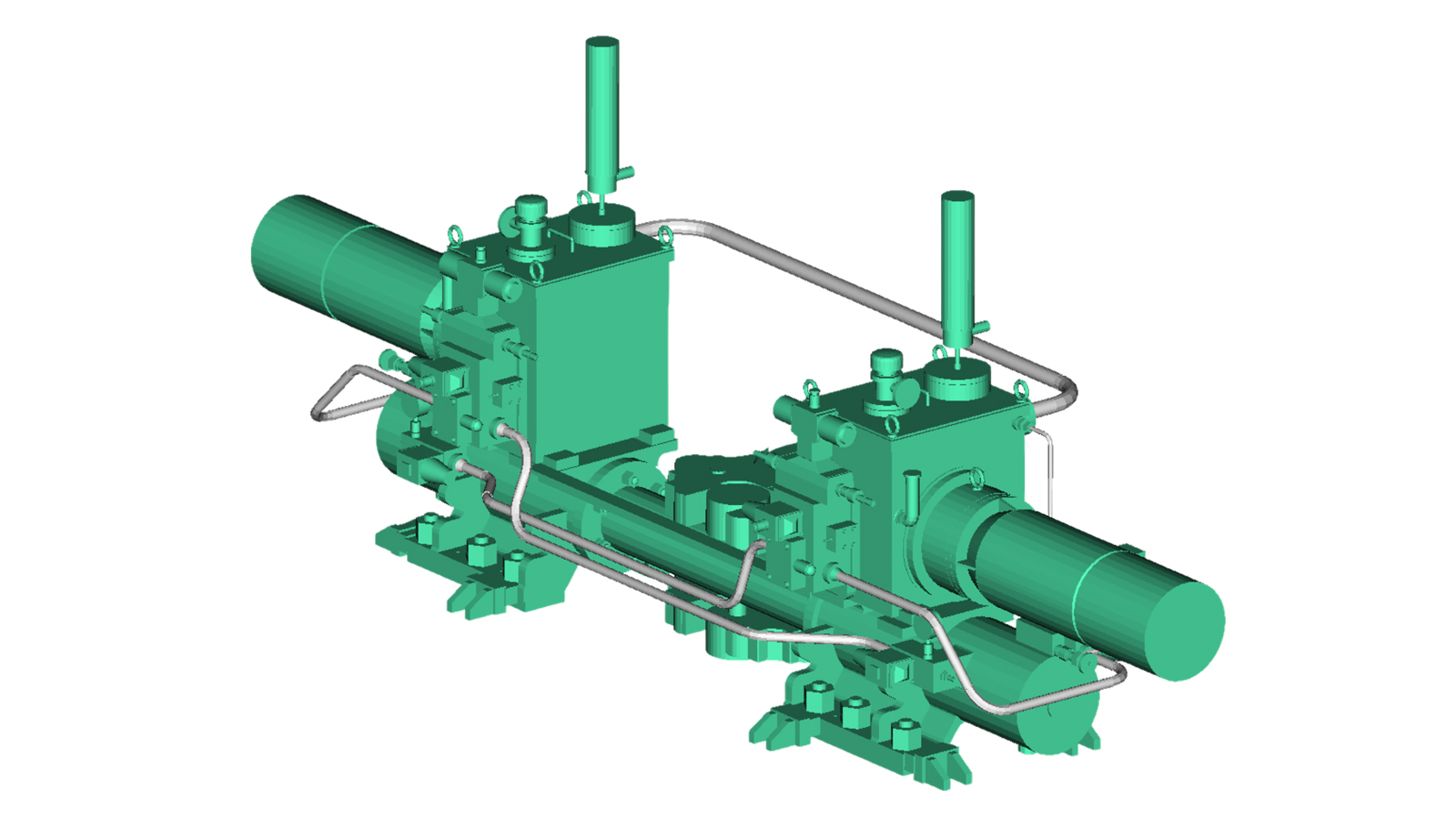
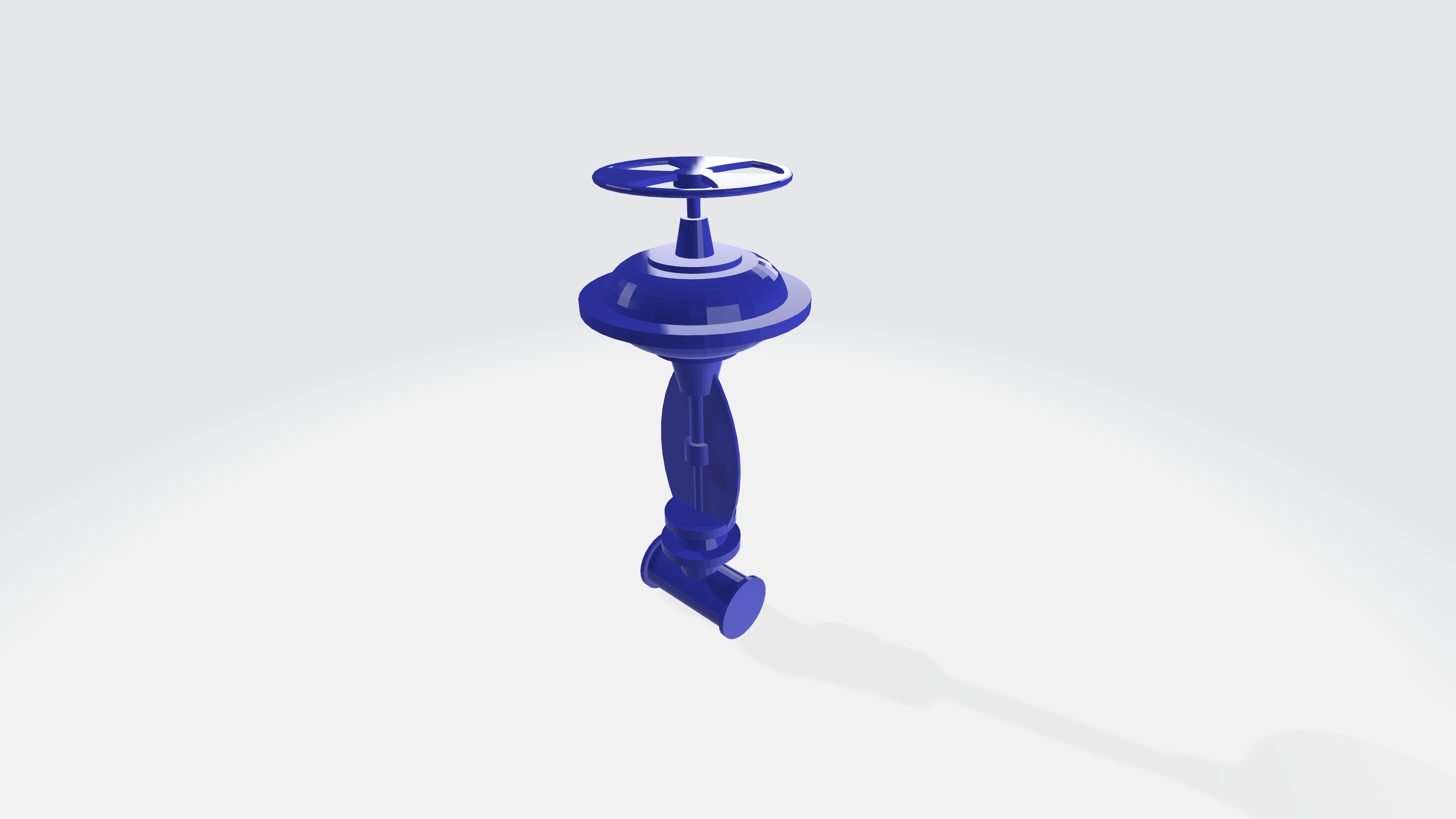
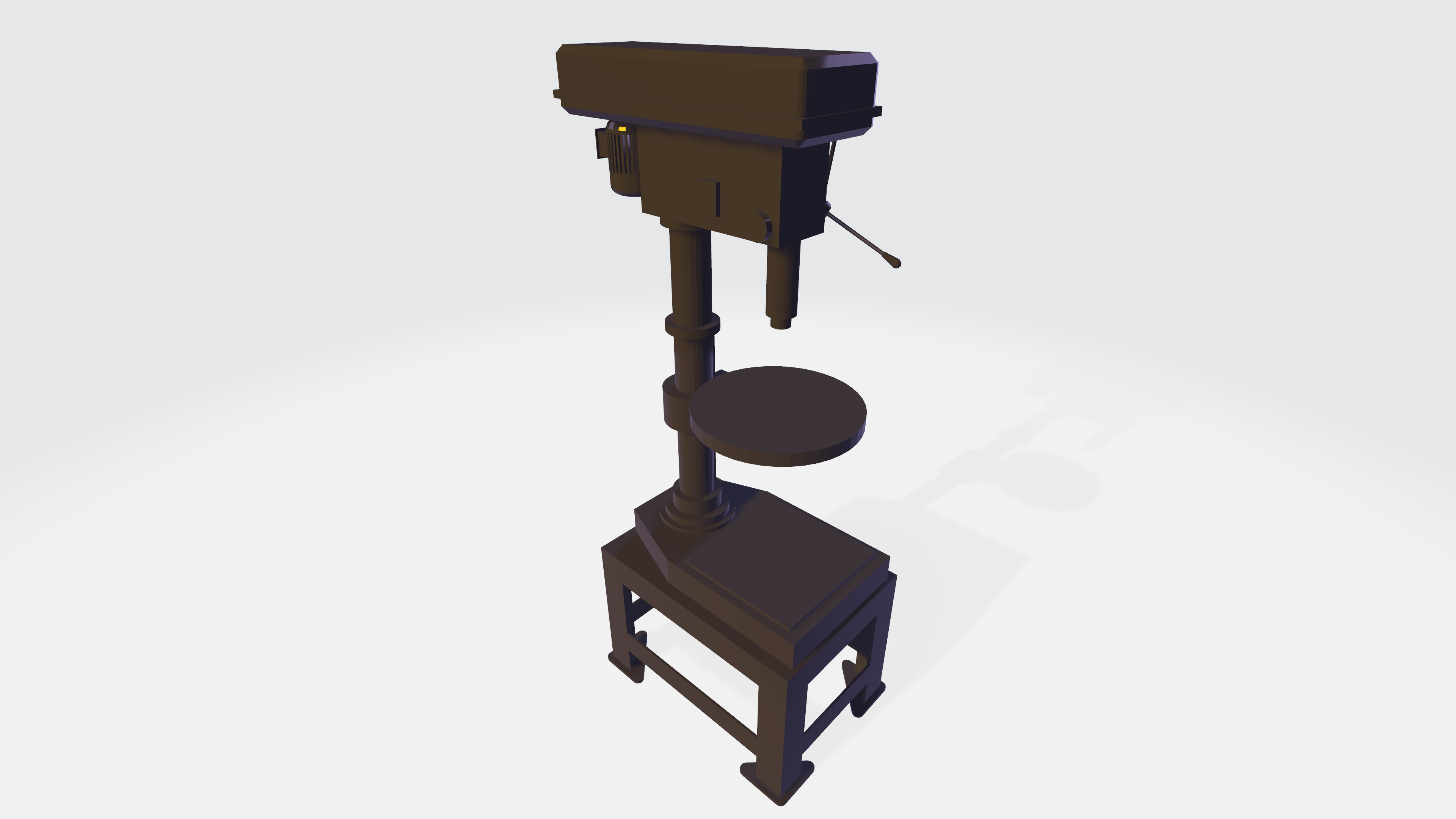
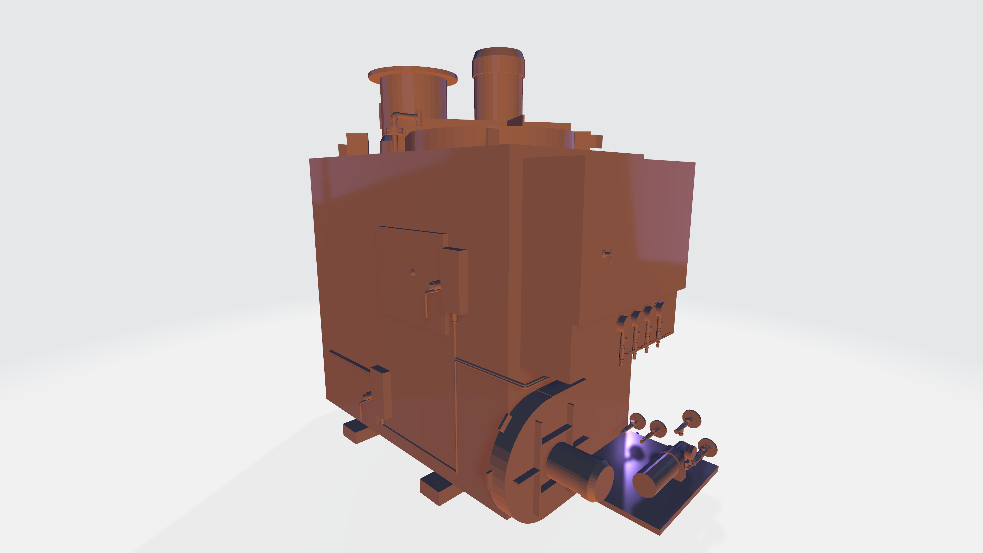
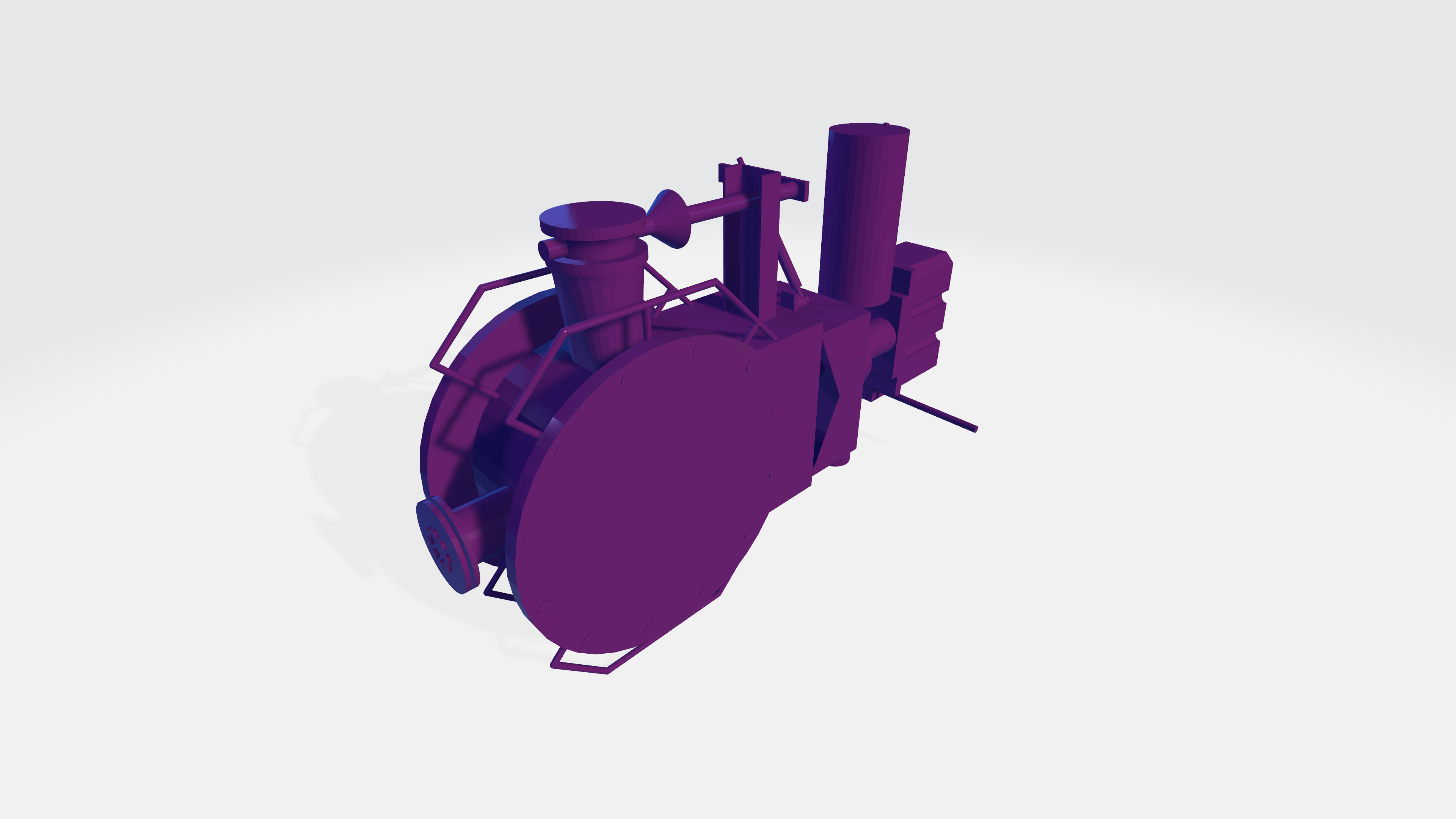
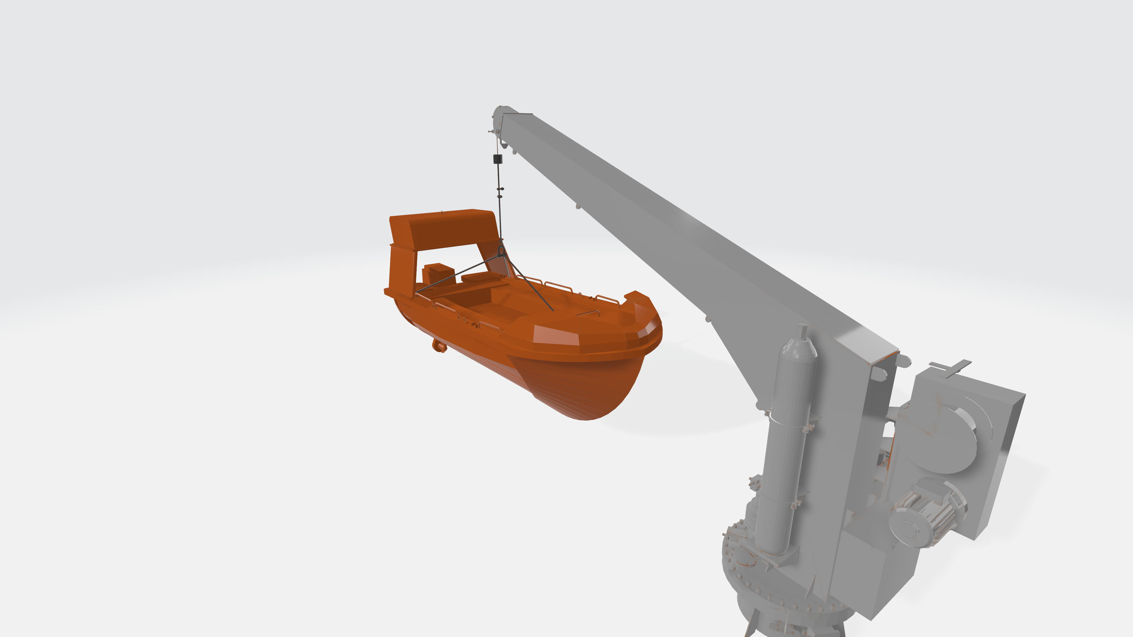
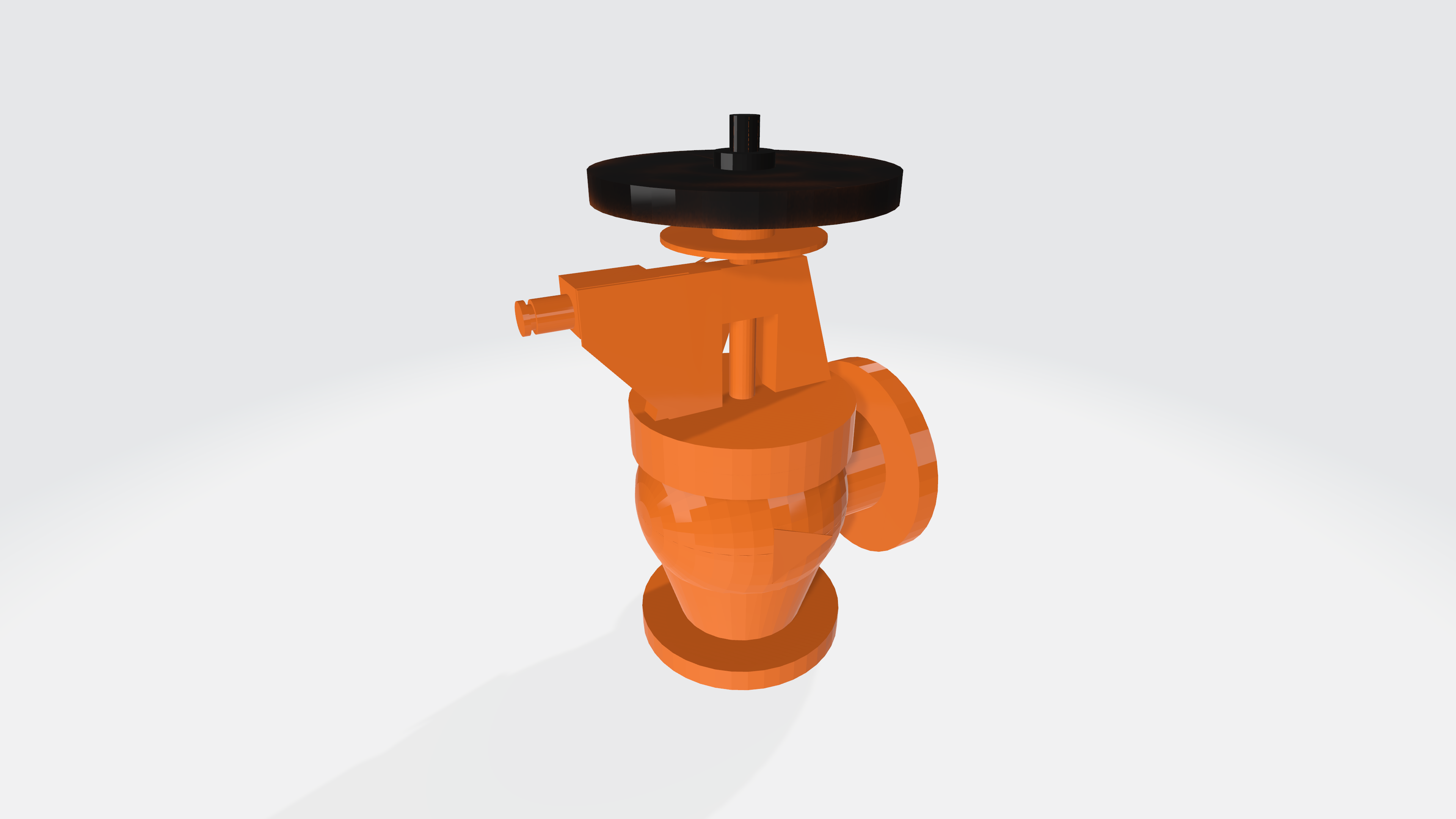
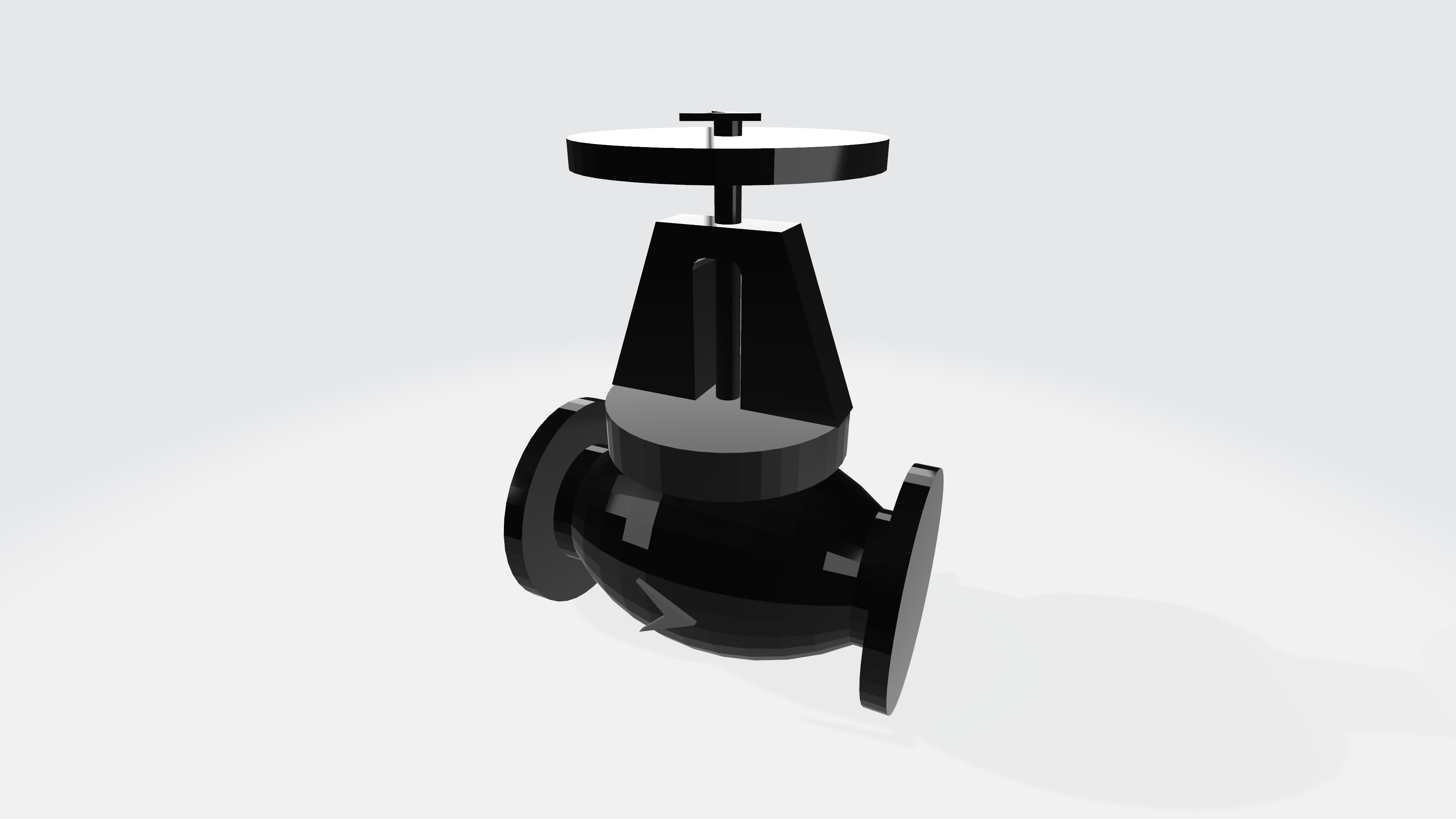
There are several equipment that needs to be installed in new-build and retrofitting projects. With the advent of 3D software in doing designs of ships and other structures, the availability of the 3D model of each equipment will make the job of the designer fast and easy.
Equipment makers can offer additional value proposition to their customers by providing a ready to use 3D models of their product.
3D MODELING
3D system is a complete and integrated solution for design of ships and other structures. A single 3D model is used from upstream design to detailing until production thus, integrity and consistency of design is ensured. Possible difficulties during installation at site can be determined through virtual review and rectified prior to actual installation. Accuracy of generated parts and pipe pieces from the 3D model is guaranteed.
3D modeling covers hull (structural), piping, outfitting and electrical.
LIBRARY CATALOGUE MAKING
Distributing design and engineering projects among locations that offer the best knowledge and cost efficiency has now become a necessity rather than luxury. TTSP has enough experience in ship detailed design and have large number of 3D-capable technical workforce. With this, we’ve managed to create our own standard library in our 3D tool.

